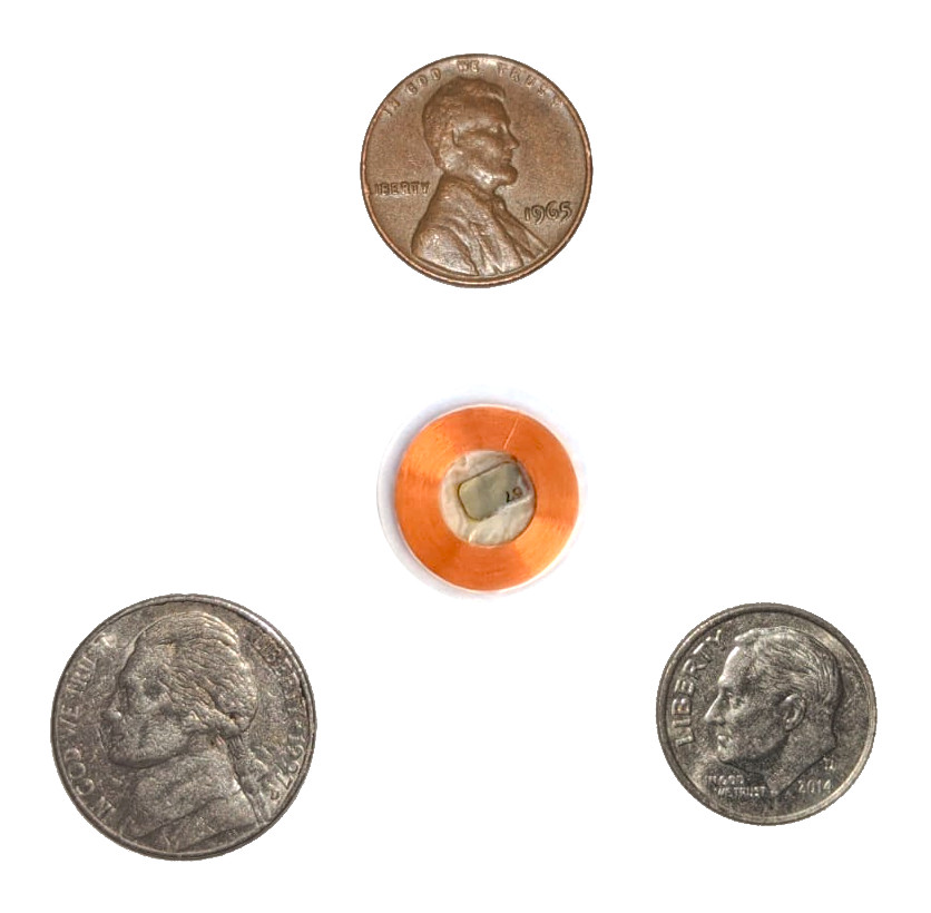



Dangerous Things xEM Access Controller v2

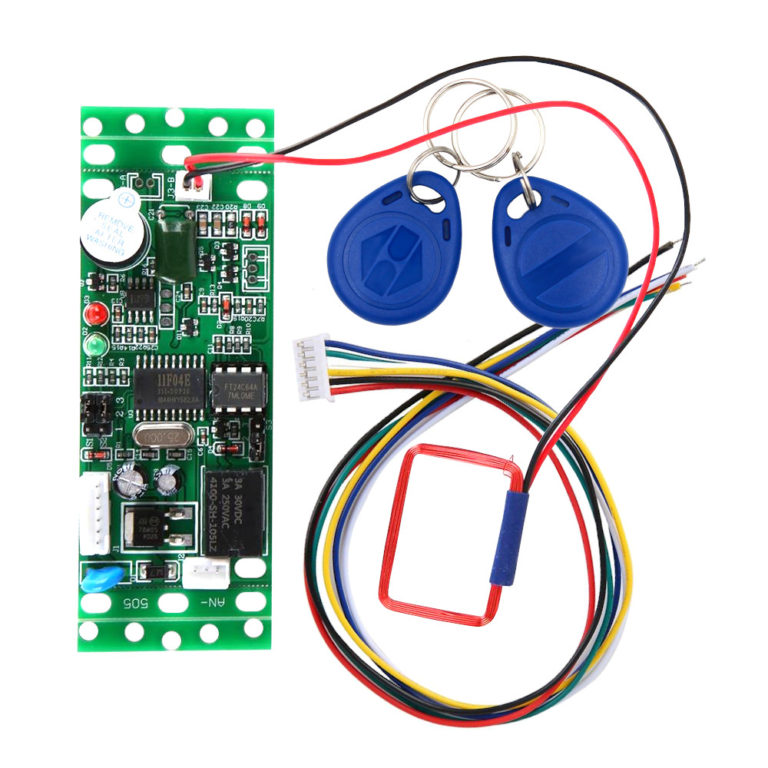
Welcome to quick and easy RFID access control projects.
-
Works with our xEM and NExT chips (in EM mode)
-
Can store up to 50 different chip IDs in memory
-
9v-12v DC operation – great for automotive projects!
-
On board relay, no need for external relay or diodes!
-
Use an onboard jumper to set your own master tags!
This is the xEM Access Controller (XAC) version 2! It’s a simple, easy to use stand-alone RFID access controller. It has a built-in EM41xx/EM42xx 125kHz RFID reader, microprocessor, SPDT relay, and memory system that allows you to easily store a list of up to 50 tag IDs in an “authorized list” within the access controller’s internal memory. You don’t need an external computer or microcontroller, this is a complete stand-alone system. When an authorized 125kHz EM tag ID is read, the relay is activated for 1 or 5 seconds, based on the S1 jumper settings. Jumper S2 allows you to program any two EM tags as add and clear master tags.
xAC v2 Details
- Operates between +9v to +12v DC power
- Reads EM41xx/EM42xx 125kHz tag IDs
- Store up to 50 RFID tags in the authorized tag list
- Easy relay wiring; common (CO), normally open (NO), and normally closed (NC)
- Two keyfobs included, can be used as add/clear master tags
- Draws 60mA idle, 102mA while relay is active
- Antenna specifics: 125kHz 543.2μH 7.93Ω
<iframe width="560" height="315" src="https://www.youtube.com/embed/A1PwCvSq8TI" frameborder="0" allow="accelerometer; autoplay; encrypted-media; gyroscope; picture-in-picture" allowfullscreen></iframe>
Wiring & Operation
Programming master tags
To get started, the first thing you will want to do is program your master tags. To do this, with the power off set jumper S2 to bridge pins 1 and 2. Next connect the black wire to ground and red wire to +12v DC power. You will see the red and green LEDs on the board blink in an alternative pattern. This means it’s ready to read the first EM tag, which will be the ADD master tag. Tap the EM tag you want to be the ADD master to the antenna. You will get a beep and the LEDs will begin blinking together in unison. This means the controller is ready to program the CLEAR master tag. Tap the EM tag you want to be the CLEAR master tag to the antenna. You will get a beep, and red LED will go solid. At this point, programming the master tags is complete. Remove power from the controller, then replace jumper S2 to pins 2 and 3.
Adding and removing tags
To program authorized tags into the controller, power up the controller. The red LED should be solid. Scan your ADD master tag to begin. You’ll get a single beep the green LED will start blinking. Scan one or more EM tags you want to act as authorized tags. You will get a set of 3 beeps for each tag that is added. Once finished, scan the ADD master tag again and you’ll get a single beep and the green LED will stop blinking. To clear tags, scan the clear master tag, then the target tag to clear, then the clear master tag. To clear all tags, scan the clear master tag, then the add master tag, then the clear master tag again. After 5-10 seconds, all tags are clear, however you must power cycle the reader to go back to normal operation.
Relay wiring and operation
The relay wires are white, yellow, and green. The white wire is the common pin on the relay, yellow is NO (normally open), and green is NC (normally closed). The common wire (white) is the relay pin that will be connected to either the NC (green) pin or NO (yellow) pin, depending on if the relay is active. In the normal state, the common (white) pin is connected to the NC (green) pin. This might be useful for keeping a magnetically locked door secure, since power must be flowing to the magnet to keep the door locked. Once an authorized tag is scanned, the relay is activated and the common (white) pin loses connection with the NC (green) pin, and instead the common (white) pin and the NO (yellow) pin are connected. Once the timer runs out, the relay is deactivated and the common pin loses connection with the NO pin and reconnects with the NC pin. To change the amount of time the relay stays active on authorized tag scan, change jumper S1. When S1 is bridging pins 1 and 2, the relay is active for 5 seconds on authorized tag scan. When S1 is bridging pins 2 and 3, the relay is only active for 1 second on authorized tag scan. It is possible to reset the timer and keep the relay engaged indefinitely by continuing to hold an authorized tag in place so it is consistently re-scanned.
Login
Accessory Items